Program Logic Control Diagram Programmable Logic Controller
Program logic diagram [diagram] 12v wiring diagram symbols list Programmable logic controllers explained
[DIAGRAM] Master Logic Diagram - MYDIAGRAM.ONLINE
Great programmable logic controller uses Plc logic programmable relay Plc logic programmable input fx1n 40mt
Ladder diagram of plc
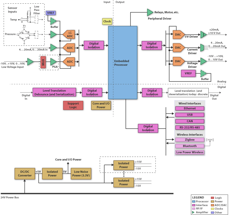
Fx1n ex1n 40mt programmable logic controller 24 input 16 input 2ad 2daLogic programmable diagram controller block embedded plc systems blocks system components ti controllers schematic building application electronic Programmable logic controller symbolsProgrammable logic controller circuit diagram.
[diagram] master logic diagramProgramming logic diagram for the master control board. Logic programmable controllers plc explained developedLadder logic flip flop plc examples programming diagram toggle off button push function program circuit example coil control bradley allen.
Logic variable irrigation
Programming logic diagram for the master control board.Logic programmable controller basics training ntt The schematic diagram of the control logic.Patent us6745254.
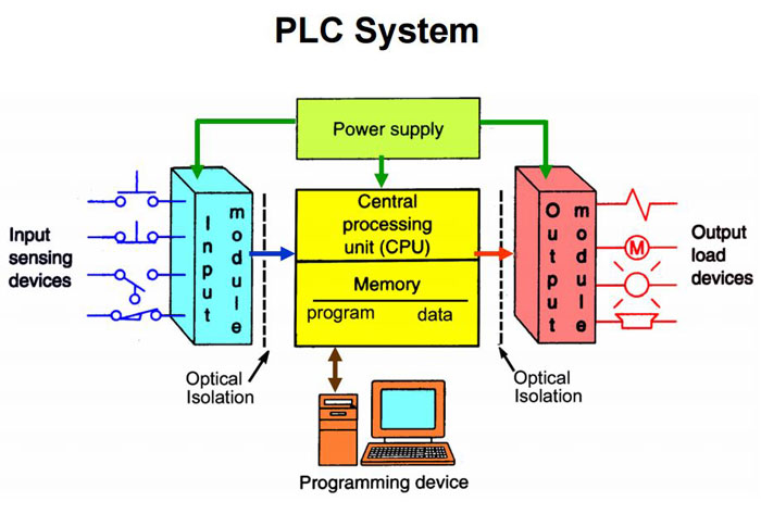
Top 4 plc in 2022Plc ( programmable logic controller ) : introduction, use, example with Programmable logic controller basicsProgram logic diagram.

Diagram logic control block whats difference between drawing simulink transform diagaram matlab wiring math strip captur kb paintingvalley researchgate post
Plc logic programmable programming beneficiallyThe critical frontier: plc security in the digital era Plc program example with toggle or flip-flop functionWhats the difference between control logic diagram and block diagram.
[explained] plc block diagramDiagram of control program logic for management of a variable-rate Figure 2 from programmable logic controller and its applicationsProgrammable logic controller (plc).

Programmable logic controller block diagram
The schematic diagram of the control logicPatents claims programmable controller logic .
.


![[DIAGRAM] 12v Wiring Diagram Symbols List - MYDIAGRAM.ONLINE](https://i2.wp.com/electrical-engineering-portal.com/wp-content/uploads/2017/01/ladder-logic-device-symbols.png)


![[DIAGRAM] Master Logic Diagram - MYDIAGRAM.ONLINE](https://i2.wp.com/www.researchgate.net/profile/Kyo_Song/publication/242368859/figure/fig4/AS:668624939384843@1536424016492/Block-diagram-of-the-system-control-logic-of-a-networked-smart-actuators-array.png)